At this year’s 2024 SPE Hydraulic Fracturing Technology Conference and Exhibition (HFTC) DarkVision presents a new approach to measuring the position and rotation of fiber optic clamps installed on the outside of casing to map fiber optic lines at sub-millimeter and sub-degree accuracy. This is 1 of 2 technical papers published by DarkVision at HFTC 2024. This paper describes the process in detail and highlights the impact it has on preventing the damage of expensive fiber optic systems installed in wells.
SPE-217819-MS
Full whitepaper available here: “High-Resolution Acoustic Imaging Deployed for Mapping Permanent Fiber Optic Lines”
Abstract
High-resolution acoustic imaging technology has been developed and deployed to map the downhole location and orientation of fiber optic lines in unconventional oil and gas and carbon capture wells. Fiber optic installations are long term monitoring solutions providing continuous measurement of temperature, sound, or strain. These fiber lines provide significant insight into the operation and optimization of downhole assets but require a large capital investment, typically upwards of a million dollars. By accurately mapping fiber optic lines, operators can prevent damaging or perforating through these costly systems during completion and production operations.
High-resolution acoustic imaging technology allows operators to directly locate and map in-situ fiber optic systems at logging speeds up to ten times faster, with high accuracy, and more efficiently than legacy technologies by overcoming the requirement to install additional costly detection components. The unique sensor probe employs a circumferential array design, comprised of up to 512 individual elements which are electronically controlled from advanced imaging software. The integration of machine vision algorithms has led to a 100% success rate at detecting, orientating, and mapping of fiber optic lines to prevent damaging these costly and critical monitoring installations.
Through a series of validation tests and field applications, this paper details how the solid-state imaging probe was used to identify the submillimetric indentations made at each fiber clamps installation. These contact points indicate the depth and phase orientation of each clamp in a well, enabling the generation of a high-resolution fiber optics system map. While legacy ultrasonic tools rely on a direct reflection principle, this novel, intra-steel imaging technology measures diffuse acoustic reflections at any point on, or inside of, the casing steel. Diffuse reflections are highly sensitive to indentations and markings on the casing surfaces; this removes the legacy-technology requirements for excessively slow logging speeds and the installation of costly steel detection bars.
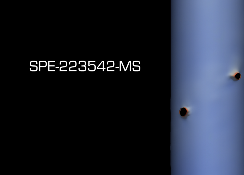
Following successful validation testing, this technology was field deployed and successfully located, oriented, and mapped all the fiber optic clamps ahead of perforating the casing of a carbon capture well. The platform imaged and mapped over 2,060 clamp contact points with a sub-radian azimuthal or phase resolution. In addition to this, high- resolution acoustics have shown fiber optic systems wrap around the casing circumference multiple times, highlighting the inability for fiber optic systems to be accurately installed and oriented. Using this dataset, the operator effectively executed subsequent perforation activities without damaging the fiber optic lines used to monitor the well and reservoir.
Paper Number: SPE-217819-MS
Authors: Trent Pehlke; Greer Simpson; Andrew Roberts; Tamara Maxwell; Julia Chu
Read the full white paper: “High-Resolution Acoustic Imaging Deployed for Mapping Permanent Fiber Optic Lines” to get the whole story.
See also: 2nd paper released at HFTC 2024
SPE-217768-MS: On Track for Refrac: Targeting Under-Stimulated Stages and Assessing Casing Integrity Defects with High-Resolution Acoustic Imaging
Updates
See all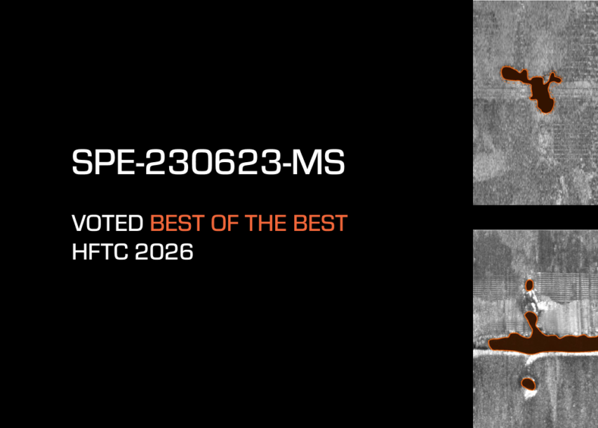
Frac Optimization: Analyzing Operational Metrics That Matter

Zooming Out: Integrating Near Wellbore Analyses to Optimize Field Performance
Adding Depth: The Superiority of Volumetric Perforation Erosion Analysis

PPIM 2025 Paper: Introducing Triple-threat Detection and Sizing in a Single Pass

Assessing the Impact of Oriented Perforating Strategies and Frac Plug Performance in DJ Basin Wells

On Track for Refrac: Targeting Under-Stimulated Stages and Assessing Casing Integrity Defects with High-Resolution Acoustic Imaging
“A Shift or Not a Shift?” Evaluating Sleeves in the latest paper by ConocoPhillips
ICoTA Woodlands 2023: Virtually Unplugging Perforations: Advanced Entry and Exit-hole Analysis
Newsletter Signup
By clicking Submit you’re confirming that you agree and consent to our Terms and Conditions.